Veins信号传输模拟
Path loss models & Obstacle Shadowing & Antenna Patterns & Vehicle Obstacle Shadowing & Antenna Patterns
在本次实验中主要使用的路径衰减模型以及建筑物对于信号传播的衰落模型。
我把需要的部分搬运了过来,原文链接在这里https://veins.car2x.org/documentation/modules/
Two-Ray Interference Model
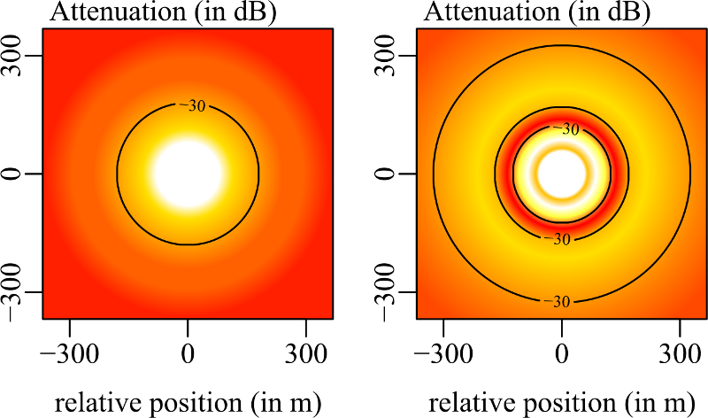
Path loss models are central to accurately modeling information propagation in a vehicular network. An often made, but wrong, assumption is that all signals propagate in close to free space conditions. In fact, particularly on linear unobstructed stretches of roads, any transmission experiences (depending on the distance) either constructive or destructive interference with its own ground reflection. Yet, the often-cited simplified Two-Ray ground model only captures the fact that (for the physics of vehicular networks), path loss increases for distances over approximately 900 meters. Veins therefore includes a Two-Ray Interference model which actually manages to capture ground reflection effects, as illustrated below.

This leads to quite different areas of good signal reception (left: two ray ground, right: two ray interference), as illustrated below in a top-down view.
Please refer to our publications for a detailed description of the model itself, including a thorough description and an evaluation.
 Christoph Sommer, Stefan Joerer and Falko Dressler, “On the Applicability of Two-Ray Path Loss Models for Vehicular Network Simulation,” Proceedings of 4th IEEE Vehicular Networking Conference (VNC 2012), Seoul, South Korea, November 2012, pp. 64-69. [DOI]
 Christoph Sommer and Falko Dressler, “Using the Right Two-Ray Model? A Measurement Based Evaluation of PHY Models in VANETs,” Proceedings of 17th ACM International Conference on Mobile Computing and Networking (MobiCom 2011), Poster Session, Las Vegas, NV, September 2011.
The model can be activated by including an appropriate
AnalogueModelstatement inconfig.xml, e.g., as follows.<AnalogueModel type="TwoRayInterferenceModel"> <parameter name="DielectricConstant" type="double" value="1.02"/> </AnalogueModel>This model is included since Veins 2.0.
Obstacle Shadowing
Radio transmissions are heavily impacted by signal shadowing effects. Accurately capturing this is particularly important in vehicular networks operating in suburban and urban environments, where buildings block radio propagation. Veins includes a simple obstacle shadowing model that has been calibrated and validated against real world measurements, as illustrated below.


This model will accurately capture the effect that large buildings will block transmissions and weak transmissions are blocked by as little as a small wall, while strong transmissions are only slightly hindered by the presence of buildings in the line of sight, as illustrated in the sample screencast below.
- Christoph Sommer, David Eckhoff, Reinhard German and Falko Dressler, “A Computationally Inexpensive Empirical Model of IEEE 802.11p Radio Shadowing in Urban Environments,” Proceedings of 8th IEEE/IFIP Conference on Wireless on Demand Network Systems and Services (WONS 2011), Bardonecchia, Italy, January 2011, pp. 84-90. [DOI]
- Christoph Sommer, David Eckhoff and Falko Dressler, “IVC in Cities: Signal Attenuation by Buildings and How Parked Cars Can Improve the Situation,” IEEE Transactions on Mobile Computing (TMC), vol. 13 (8), pp. 1733-1745, August 2014. [DOI]
The model can be activated by adding an ObstacleControl module to the simulation and including an appropriate SimpleObstacleShadowing statement in config.xml, e.g., as follows. Aside from the ObstacleControl module offering the possibility to manually add obstacles to the simulation, the TraCIScenarioManagerLaunchd will automatically detect the presence of an ObstacleControl module and automatically instantiate one obstacle per polygon of type building in SUMO.
<AnalogueModel type="SimpleObstacleShadowing">
  <parameter name="carrierFrequency" type="double" value="5.890e+9"/>
</AnalogueModel>
How to use these modules is demonstrated in the source code of the Veins tutorial example.
This model is included since Veins 1.99.2.
Vehicle Obstacle Shadowing
A simulation model of radio shadowing effects caused by other vehicles has recently been completed.
Please refer to our publication for a detailed description of the model itself, including a thorough description and an evaluation.
- Christoph Sommer, Stefan Joerer, Michele Segata, Ozan K. Tonguz, Renato Lo Cigno and Falko Dressler, “How Shadowing Hurts Vehicular Communications and How Dynamic Beaconing Can Help,” IEEE Transactions on Mobile Computing (TMC), vol. 14 (7), pp. 1411-1421, July 2015. [DOI]
The model is included since Veins 5.0.
Antenna Patterns
A simulation model that captures angle-dependent gains of antennas has recently been completed. It includes parameters for different types of real-world antenna patterns, depending on antenna type, mounting point, and roof topology. An antenna pattern can be configured by setting a physical layer’s antenna parameter to an XML statement configuring the type of antenna, along with type-dependent parameters. If no antenna pattern is specified, the physical layer defaults to 0 dBi gain isotropic.

At the moment, only one antenna pattern type, SampledAntenna1D, is implemented. It defines an antenna pattern using a single parameter, samples, which stores a series of gain samples, taken at equidistant intervals from 0 degress, going clockwise. This antenna also takes optional random-offsets and random-rotation parameters to add a random gain offset (in dBi), as well as a random rotation offset (in degrees) to each antenna.
The following is an example XML statement configuring such an antenna using very coarse (four) gain samples (+2.0 dBi to the front of the car, +1.1 dBi to the right of the car, -4.0 dBi to the back of the car, +0.9 dBi to the left of the car). This XML statement also applies a random +/- 1 dBi gain to each antenna, as well rotating the whole antenna pattern by a random +/- 1 degree.
<Antenna type="SampledAntenna1D" id="patch">
  <parameter name="samples" type="string" value="2.0 1.1 -4.0 0.9"/>
  <parameter name="random-offsets" type="string" value="uniform -1 1"/>
  <parameter name="random-rotation" type="string" value="uniform -1 1"/>
</Antenna>
Please refer to our publication for a detailed description of the model itself, including a thorough description and an evaluation.
- David Eckhoff, Alexander Brummer and Christoph Sommer, “On the Impact of Antenna Patterns on VANET Simulation,” Proceedings of 8th IEEE Vehicular Networking Conference (VNC 2016), Columbus, OH, December 2016, pp. 17-20. [DOI]
The model is included since Veins 4.5.